I'd always been interested in this kit, and in 1997 (after I started getting regular paychecks), I started thinking that my kit-built locomotive really deserved an SP-style tender. I did some research, ordered the parts, and started trying to build a tender of my own. My big problem was that there were no instructions; I wasn't sure how to build the kit, and wasn't sure how to fabricate the parts that are no longer available. Worse, I had little experience with metalworking, so the project's always been on a shelf.
Luckily, a few lucky breaks happened. I found an assembled Kemtron kit with instructions at a swap meet. My wife took a jewelry-making class and learned how to properly use a jeweler's saw. I kept being jeered by that unfinished set of parts in a box. Finally, after about ten years of waiting, I've finally built my Kemtron tender.
In case you're been interested in this tender, here's some details about the kit and hints on how to build your own.
The Tender
The Kemtron kit resembles a 100-C-5 Southern Pacific tender, but it isn't an exact model. It has slightly different dimensions, appears to ride a bit high, and has trucks that only appear under larger tenders. The tender diagram in the SP Historical and Technical Society's tender diagram book shows the 100-C-5 tank as 31' 4" long where the Kemtron tender is 32' long; the oil bunker on the Kemtron tender (as sized from the tender front and top castings) is also different; on a 100-C-5, the oil tank is 6' high and 10'6" long; the Kemtron oil tanks is 5' 6" tall and 10' 8" long. The 100-C-5 has an overall height of around 12', while the Kemtron ender ends up at about 12'8.
I ended up adjusting the dimensions of my model to match the 100-C-5 tender where I could. Generally, overall length and height could be adjusted easily by changing the length of the water tank and adjusting the position of the oil tank.
The Parts
The first step is to collect the parts. When I was shopping back in 1997, the brass castings for the kit were still available individually from Precision Scale, but all the etched and sheet pieces weren't. Some of the parts appear to have since gone out of production, but many might be hiding in the parts bin of your favorite model railroad store. The entire list of castings is:
3050 toolboxes (2)
3115 Rerail frogs
31084 running boards
31257 front and rear sills
31325 Vanderbilt tender rear ladders and front steps
31399 steam and air piping
31509 tank top
31510 tank front (top section), Vanderbilt oil tender
31511 tank front (bottom section), Vanderbilt oil tender
51512 tank rear, Vanderbilt oil tender
31513 oil filler cap
31514 tank platform with manhole covers
31541 Commonwealth tender trucks
31644 Vanderbilt tender tank steps
brake wheel
Several other parts were listed in PSC's catalog -- etched parts for the tank cylinder, the oil tank sides, and the front apron. The catalog also lists a built-up underframe (though the instructions I saw insist you'd have to fabricate your own frame from brass bar stock.) To build the kit, you'll need to fabricate these yourself.


Kemtron instructions (click on image for scan of whole page) / Built-up Kemtron tender found at a railroad show
I picked up the castings from Walther's via mail-order and hobby shops. I found the etched front apron part at the Hobby Gallery in Wolcott, CT. They used to buy old stock from other hobby shops, and so had a nice selection of old parts.
Building the Kit
Most of the assembly work matches what you'd do when building a locomotive or tender out of brass. The Model Railroader magazine series on building brass locomotives in 1982 and 1998 give details on this that are better than anything I could provide. However, there were a couple of trouble spots to keep in mind.
I had to make some parts myself -- the water tank body, oil tank sides, and frame. The tank body isn't as difficult as it looks. The tank body is brass sheet; I used 0.015 inch brass, though the castings were designed for 0.025 brass. The tank end and oil tank castings stick out a bit too far because I was using thinner metal. If I was doing the model again, I'd probably insert 0.010 brass strip under the wrapper so that the tank end and tank side castings don't stick up past the fabricated parts. I embossed rivets in the sheet with a Northwest Short Line Riveter tool; I tried doing this by hand in the past, but never liked the results. I then rolled the tank's cylinder by bending it over a dowel in a vise. When the tender was in the right shape, I filed the two ends to meet perfectly, bent the tank so it would stay in shape, wrapped some florist's wire around it to hold it in a cylinder shape, then soldered the bottom seam to make my cylinder. I also used the riveter to emboss the side and back sheet for the oil tank.
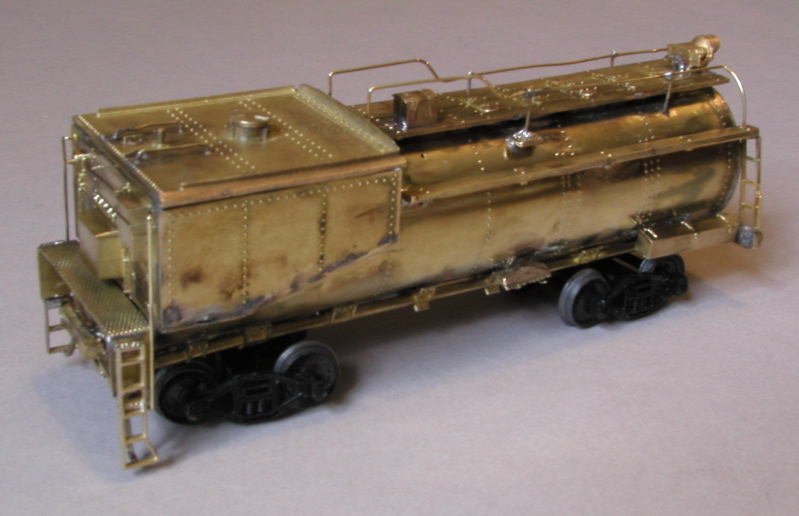
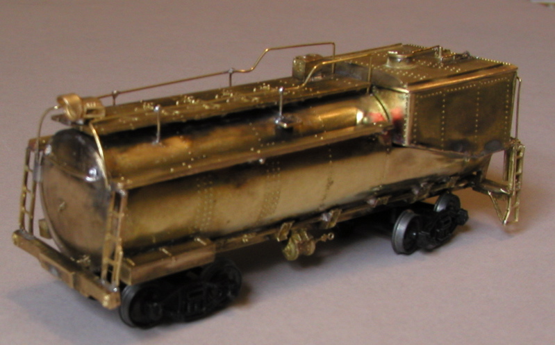
Final result before painting -- front and back
The rest of the assembly involved soldering parts on. One difficult part was attaching the running boards and single steps on the tank. Both have brackets to attach them to the boiler, but the brackets all need to be bent at an angle to fit against the tank. I couldn't bend the running board brackets without breaking them; I had better luck with the steps. For the running boards, I used 0.032 inch brass rod as pins to attach the running boards.
I also had problems getting the running boards and rear ladders to fit appropriately. When I first soldered the end, the ladders were too far apart, and the running boards wouldn't have touched the tank. I eventually adjusted things, but my tank was long enough that the running boards didn't quite reach the whole length of the tank. As a result, the rear ladders slope forward too much and hit the tank end. Making the tank shorter would have been better.
Finally, the instructions point out you'll need to grind off parts of the steam and air pipes for wheel clearance. It's easier to cut these off with a jewelers's saw before soldering them in place. I didn't, and got to spend an enjoyable half-hour using a cut-off wheel and trying to ensure I kept all my fingers and didn't scar the completed tender.
I also found it hard to set the heights of everything, so I ended up making myself a simple surface plate and surface gauge so I could scribe level lines on my boiler. My surface plate is merely steel sheet attached to a particle board base, and my surface gauge is made from brass tubing and sheet.
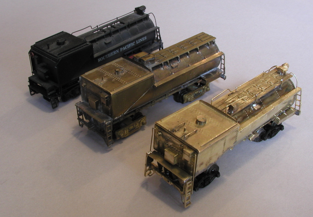
Here's a comparison of a Westside 100-C-5 tender, the Kemtron tender I found, and my tender:
Designing in Access for a Decoder and Sound
One of my pet peeves with Vanderbilt tenders is that they're usually sealed shut, so placing DCC sound decoders in the tender can be near-impossible. To make it easier to install the speaker, decoder, and wires, I made the oil bunker removable as seen in the photos. It's harder to finish the edges of the tank (and in fact my tank doesn't quite fit level), but it'll be a great improvement over trying to wedge all the sound decoder parts through the top of the oil bunker.
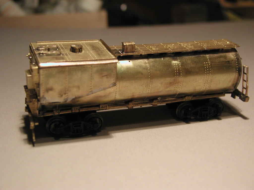
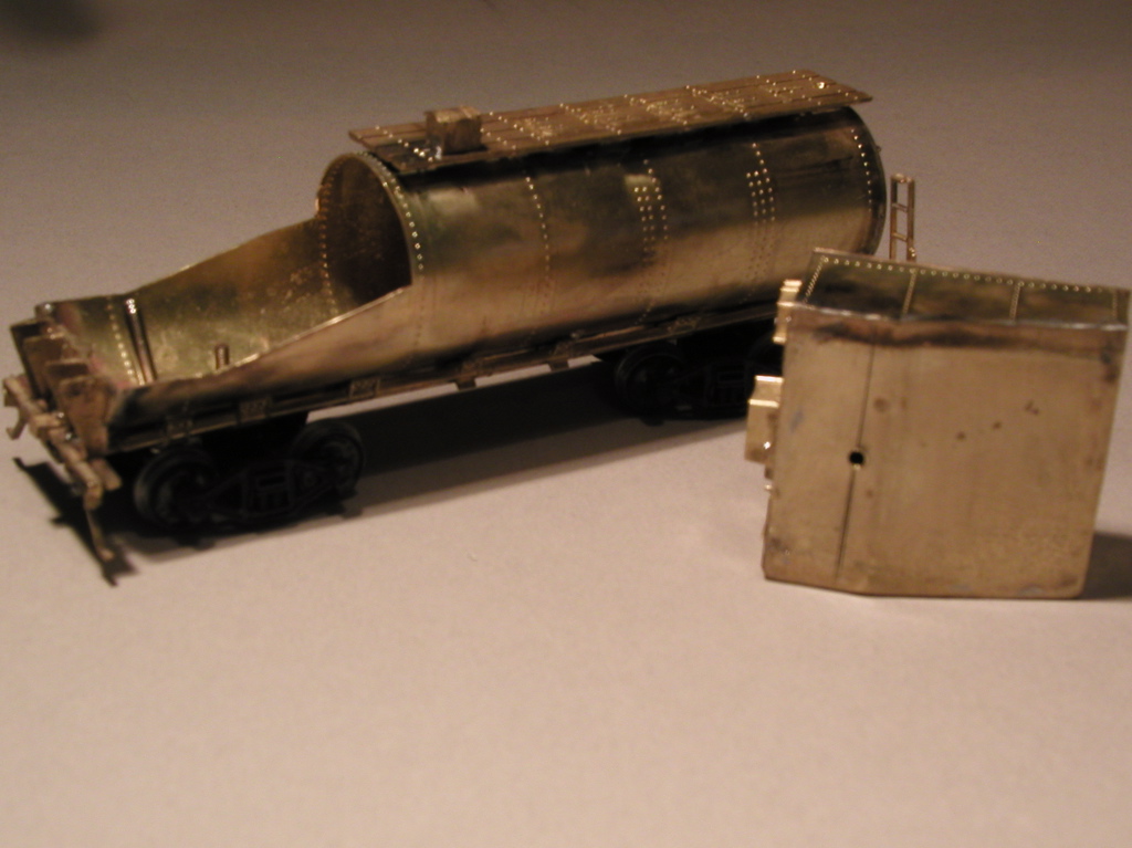
My Kemtron tender under construction / Removable oil bunker will make a sound decoder easy to install
Still To Come
Work still to be done includes adding the DCC decoder, painting, and assorted fine tuning.