- On a single track line, a train will see signal indications for the blocks ahead. Three color signals (red, yellow, and green) are allowed to inform the engineer that although the next block is empty, the signal after will be red.)
- All signals from a passing siding to an occupied block are red to avoid an opposite train using the same line.
- Signals go red if a passing siding's switch is set to the siding instead of the main.
ABS style signalling was particularly useful to allow following trains to keep separation.
For modeling and operation, I wanted to install the signals. Partly, I just thought it would be fun to experiment with the signal logic and do the wiring. I also knew that signals (especially semaphores) would add life to the layout. Having signals on a train-order branch also makes multi-section trains possible. I could complicate operation by having freight trains run as the second section of a passenger train, and force meeting freights to understand the rules on sections.
Using the SIC 24 to Control Signals
I didn't want to run the signals on DCC; I didn't want to have a separate booster for signals, and didn't want the added complexity on the DCC side. The Team Digital SIC24 signal controllers were perfect. These are simple computers that can be programmed to watch inputs from switch settings or block train detectors, and turn on or off signal lights as appropriate. I liked that these were completely programmable; you could set them up to do whatever you wanted (within the SIC 24's abilities.) The SIC 24s can also be linked with phone cables to react to changes on inputs from other SIC cards. SIC 24s could light LEDs, or could also directly control low-current-stall switch motors like Tortoises. They could also control semaphores and bi-color LEDs (which can show red, yellow, or green depending on the voltage sent to the two wires.)
The SIC24 has its confusing points. First, each input and output gets numbered, and those numbers are in the same "space" (meaning having an input and output both numbered 1 won't work correctly.) In my case, I set up the first SIC24 so that its inputs are 1-8 and its outputs are 101-124. The second SIC24 is set so its inputs are 9-16 and outputs are 125 to 148. The logic can react based on changes in an input or from another output.
Being able to have an output dependent on inputs or other outputs means that controlling red/green signals is easy. For example, the switch motors work by flipping the polarity on the two outputs going to the switch motor. If one output is "off" (and at voltage 0) and the other is "on" (and at +5v) then the switch motor moves one way. If I reverse the outputs so the first is off and the second is on, then the switch motor moves the other way. It's also easy to make temporary signals by soldering a red and green LED to each other in opposite directions, and adding a resistor to one of the outputs to limit the current going to the LED.
"Output 123" (which I've set up to be the last output on my first SIC 24) can be set to turn on (and turn an LED red) if input 1 is on:
Output 123 = input 1 is HIGH
To make my signals work well, I can set output 124 (the other contact for the LED or Tortoise) to do the reverse:
Output 124 = output 123 is LOW
Controlling bi-color LEDs isn't straightforward. When all the SIC24 can do is "on" or "off", how do you make two outputs handle the three cases (red, green, and yellow)? First, we need to understand how the outputs need to be set:
Green: output 1 off, output 2 on (phase 2, so only on half-bright)
Red: output 1 on (phase 1), output 2 off.
Yellow: output 1 on (phase 1), output 2 on (phase 2) causing output to flash red,green.
So, to do green, we need:
output 1 = Red or Yellow
output 2 = Yellow or green
All we need to do is make sure that output 1 is on if we want to display red or yellow, and off if we want to do green, and we want output 2 to be on if we want to display yellow or green, and off if we want to display red. If we're only doing a simple block signal (where input 1 is the next block, and input 2 is the block after that), then the outputs need to be set as:
output 1 = block 1 OR block 2
output 2 = (not block 1 AND not block 2) OR block 2
We can simplify this logic even further. Output 2 can be simplified down to "not red", which we could code as "not block 1" because that is the only condition that could cause us not to display a yellow or green.
(I have tried this logic, and it works.)
Cheap Signals
Running semaphores on all blocks was going to be expensive. I needed at least 16 signals, some of which would need to show three indications. With each semaphore costing around $60 (with the mechanical parts and the Tortoise switch machine), that was going to be some serious money. I wanted to keep costs low, have fun immediately, and not have delicate semaphores around when I was building scenery or doing other heavy work.
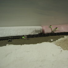
The pretty signals
I used an inexpensive trick seen when helping high school kids build robots from Legos. The part kits they got included a bunch of electrical components, usually insulated with lumps of hot glue. For my signals, I followed the same idea:
- solder two LEDs together in opposite directions so polarity would control whether they were red or green.
- solder wires to the two LEDs as close to their bodies as possible.
- cover the wires in hot glue, especially between the two wires of the LEDs and on the exposed bits of metal.
- cut or melt off the parts that look too blobby.
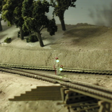
These signals might not be the most attractive, but they're cheap to make (60c each), easy to build from parts at Radio Shack or another electronics store, and they immediately get me up and running on signals. It's also easy to cut the wires and attach them to a Tortoise as I want to get semaphores running.
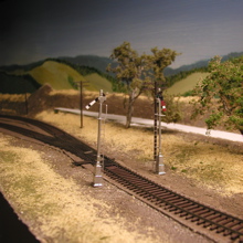
The ugly signals
Thanks to the ugly signals, I now have working signals from Los Gatos to the end of the layout. Now I just need to set up operations so someone will need to use those signals!
Adding LEDs to Class 5's Searchlight Signals
A few places on the layout won't get semaphores. Either there isn't room under the layout for the mechanism, or there's no easy access to install and adjust the semaphores. In those cases, I use searchlight signals - signals with a single circular target and light that change color. These signals match SP practice; many signals along the Vasona branch in the late 1930's were searchlight signals, so I don't feel like I'm being unprototypical. I had an old NJ International brand signal from childhood days that currently protects Vasona Junction, but I've been on the lookout for some current manufacturer of decent signals that won't cost me too much.
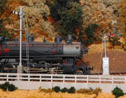
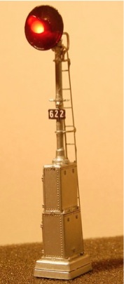
The hobby store recently started carrying SP-style searchlight signals manufactured by Class 5 in Santa Rosa, CA. The signals are plastic and metal kits. These signals aren't designed to hold a bulb; they are intended to be static models. I modified one of these signals to hold a bi-color LED (that shows red or green), and installed it at Wrights.
To put an LED in one of these signals, I had to leave out most of the signal head parts. I used the round target and the lens hood, but left out the rest of the parts. I took a T3-style bi-color LED (Minatronics, available at the hobby shop), cut the wire leads slightly, then pressed the LED into the chuck of a Dremel. (The LED press-fits nicely into the standard chuck even without tightening.) I then ran the Dremel and filed the outside of the LED til it fit through the hole in the brass target. Finally, I cut one lead short and soldered a thin wire on it that would run through the signal's mast (brass tube). I bent the other lead so I could solder it onto the mast, and ensured the LED would end up at the correct place to look like the lamp assembly.
Here's some pictures of the constructed signal:
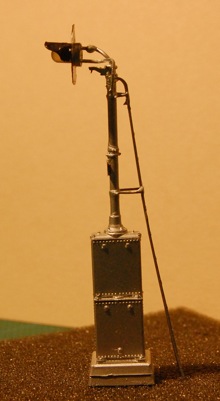
Finally, here's the signal in place at Wrights. A semaphore signal wouldn't fit in this location. The benchwork below the signal is boxed in to support the nearby canyon bottom. Although I can reach under to fish wires in and out, there's no room for the semaphore mechanism.